

How To Repair An Alternator Bearings On Chevy Suburban
A popular course of operation upgrade revolves around applying current technology to older machines. While everybody else focuses on iv-digit-horsepower LS engines with giant turbos or superchargers, let'southward go on our goals far more street-worthy and practical.
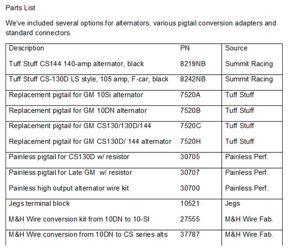
Amid the most overlooked aspects of swapping late-model engines into early Chevys is upgrading the charging system. Information technology was in the early on '60s when alternators replaced generators. Since then, a landslide of charging system and alternator enhancements have followed. We decided we needed to focus our attending on some of the more popular alternator conversions and wiring harness modifications necessary to accommodate them. We wanted to get input from a few professionals in the world of automotive charging, so we reached out to Tuff Stuff Performance and Painless Operation.
On the dorsum of GM alternators, yous will find a two- or four-wire plug along with a large output stud. The large stud is for the output wire connection that is connected to the battery positive post.
Variations On Charging
There are at least a dozen or more than variations within the family tree of GM alternators, but nosotros'll condense them downwards to an essential iv. The best way to upgrade the charging system on a '60s or '70s Chevy is to step-upwardly to the latest model versions like the CS130D. Even a stock replacement CS130D will offering more power at low speeds than previous models. That'southward simply i thought. Other alternatives that too work well.
Earlier we get into the swap details, it'due south benign to investigate charging-output numbers. In nearly all cases, alternators are rated past maximum potential-amperage output. This is not amperage delivered while at idle! Based on multiple factors — like alternator design and pulley ratios — an alternator's output at idle can be far less than its maximum rating. The original 10-DN externally regulated alternator is probably not capable of much more than than 35 amps at idle. Dorsum in the days of AM radios, that was enough to maintain system voltage.
We spoke with Mike Stasko, marketing managing director for Tuff Stuff Performance, and he has a recommendation. "Once you determine the amp requirements of your vehicle, check to see if in that location is a higher amp alternator in the same alternator series. It's always easier to swap out a low-amp alternator with a loftier-amp unit as compared to adopting a different-serial alternator."
Non All Alternators Are Created Equal
Belatedly-model alternators are far more efficient at idle, so a stock 100-amp alternator might be capable of sixty to 65 amps at idle. But let's look a lilliputian closer. Alternator rating numbers are generally tested with the alternator at ambient temperature. Unfortunately, with the charging system at normal operating temperature, internal resistance increases with heat, and the output drops, typically by 15 to twenty per centum.
If you take an alternator rated at 100 amp at idle, its normal operating temperature is probably capable of only around 75 to 80 amps. That's something to recall about if your twin electric fans and other electrical devices combine to pull more lxx amps. The net effect is a loss of arrangement voltage at idle.
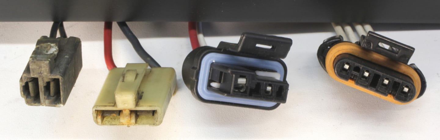
These are the 4 well-nigh common alternator connectors. If you are non sure which alternator you have, the connector shape is a adept indicator of alternator configuration. From left-to-right: 10DN, 10/12SI, CS130/CS144, and CS-130D.
"If changing to a different alternator series, brand sure the belt(s) line upwardly and the wiring is in expert condition," Mike states. "An alternator with a higher amp output than stock requires a heavier charge wire (the wire that connects the alternator to the battery) because of the increased amperage."
To evaluate your charging organization, try this simple experiment. With the engine idling at operating temperature, plough on all the electrical components such equally the headlights, blower motor at full speed, four-way flashers, electric fans, and the stereo at a reasonable level. Then, note the electrical organisation operating voltage. If the voltmeter reads below 13 volts, none of the electrical devices — including the cooling fans — are running at peak efficiency. They need a minimum of 13.5 volts.
All About The Connections
Assuming you desire to upgrade, we'll take a couple of the more than mutual options and run through the wiring variables. The original 1960'south GM alternator employs an external voltage regulator. This alternator (10-DN), uses a flat, two-prong connection at the back of the alternator. The other main connectedness on the alternator is the output last that charges the battery.
The least expensive upgrade from the 10-DN would be to step upwardly to a 10-SI or 12-SI. The master reward of either unit is they employ an internal voltage regulator (SI stands for system integrated). Only this is not a simple bolt-on conversion. The 10- and 12-SI units use a dissimilar 2-wire connector plug on the rear of the alternator. The Number 1 wire on the 10- or 12-SI is connected to the charge warning light on the dash. The Number 2 wire is what is called the voltage sensing wire.
When converting from an external voltage regulator to an internal such as the 12-SI, many enthusiasts only connect the Number 2 voltage sensing wire directly to the output terminal. While this shortcut is simple and functional, it will non optimize the charging system. The voltage-sensing wire is best connected closer to the battery.
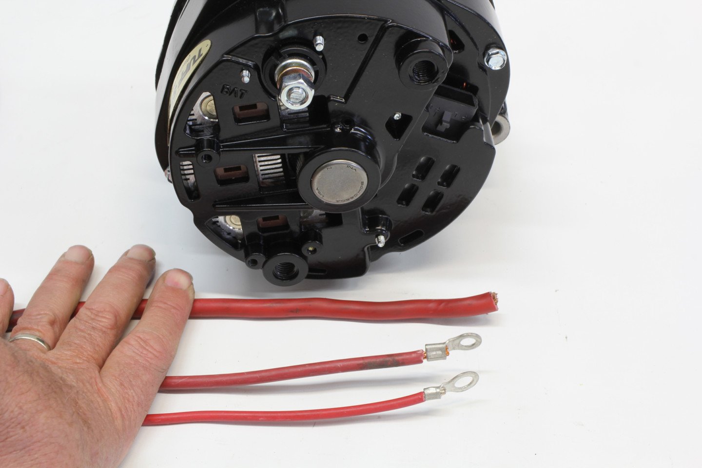
High-output alternators (greater than 100 amp) need a minimum of an viii-or-larger guess charge wire to reduce resistance. The bottom wire is AWG 12, the middle is AWG ten, and the largest is AWG 6. The largest is always better (although clunky in appearance) for minimal resistance for alternators putting out more than 100 amps.
Here's why using a remote voltage-sensing connection is a wise move. The primary charge wire on the back of the alternator is eventually tied into the positive post on the battery. However, this connexion is often a long wire. This cable length creates resistance that can be easily measured with a simple charging arrangement efficiency examination.
With the engine at idle — and several components like headlights, electrical cooling fans, and perhaps the heater fan, operating, compare the voltage readings at the alternator to those at the bombardment. In that location will generally be a slight voltage drop at the battery of around 0.50 to 0.60 volt. By locating the voltage-sensing wire closer to the battery, the alternator tin recoup for this slight drib in voltage and maintain the overall electrical organisation at around fourteen volts. With the voltage-sensing wire connected to the output final, this one-half-volt drop is not measured and the entire charging organization under-performs.
Singled Out
This is also a adept place to mention 1-wire alternators. These aftermarket alternators eliminate the warning low-cal and voltage-sensing wire connections all OE alternators use. Voltage sensing is accomplished internally, which (as we just covered) is one reason why 1-wire alternators are not every bit efficient as a remote-sensing alternator.
Some other small-scale disadvantage to one-wire alternators is the rotor in the alternator must attain a certain speed to self-excite. This usually requires the commuter to rev the engine to increase internal voltage to sufficiently excite the alternator to begin charging. This isn't a huge issue. But, you need to be aware of this and rev the engine afterwards information technology starts to ensure the charging system is functioning. Remote-sensing alternators are capable of charging the moment the engine starts.
This is a Tuff Stuff illustration of how to convert a typical mid-'60s 10DN alternator to a much more than robust CS-130. Tuff Stuff as well sells a plug-in harness that will accomplish this based on whether the automobile has a alert light or non.
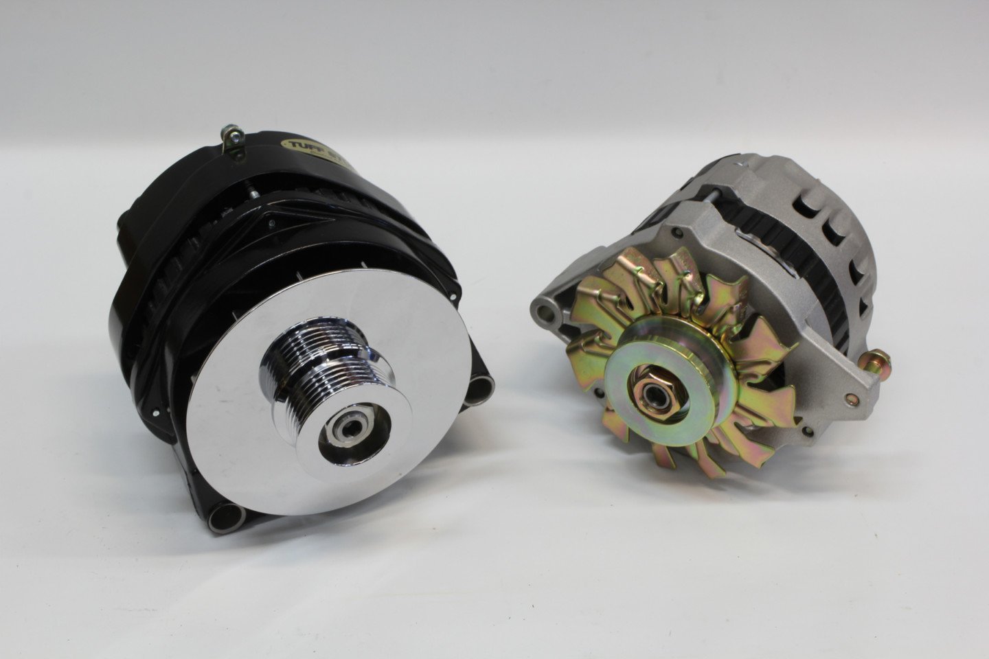
Amidst the available charging-system alternatives, you can choose to merely upgrade to a college output alternator inside the same blueprint every bit your existing alternator, or update with a after model unit with more output. The simplest would be to upgrade your current alternator. For example, Tuff Stuff Functioning offers a college output 10-DN pick. Retaining a 10-DN with the separate voltage regulator might be a good idea for those who want to retain the original appearance — for restoration purposes. If that'due south non important, it'south ordinarily ameliorate to increase output and efficiency by stepping up to a newer model alternator like a CS-130 or larger CS-144.
Some Resistance Required
Let's get through an example of upgrading a '67 Chevelle with a 383ci small-block that has been converted to a CS-130 alternator. The car retains the original factory 10-DN external-regulator wiring. One thousand&H Wire Fabricators can build a plug-in-replacement forward-lamp harness that integrates with the new alternator by only plugging information technology in. This is the cleanest way to upgrade. Equally a less expensive culling, Painless Wiring offers a replacement CS-130 pigtail connector that can easily be spliced into place.
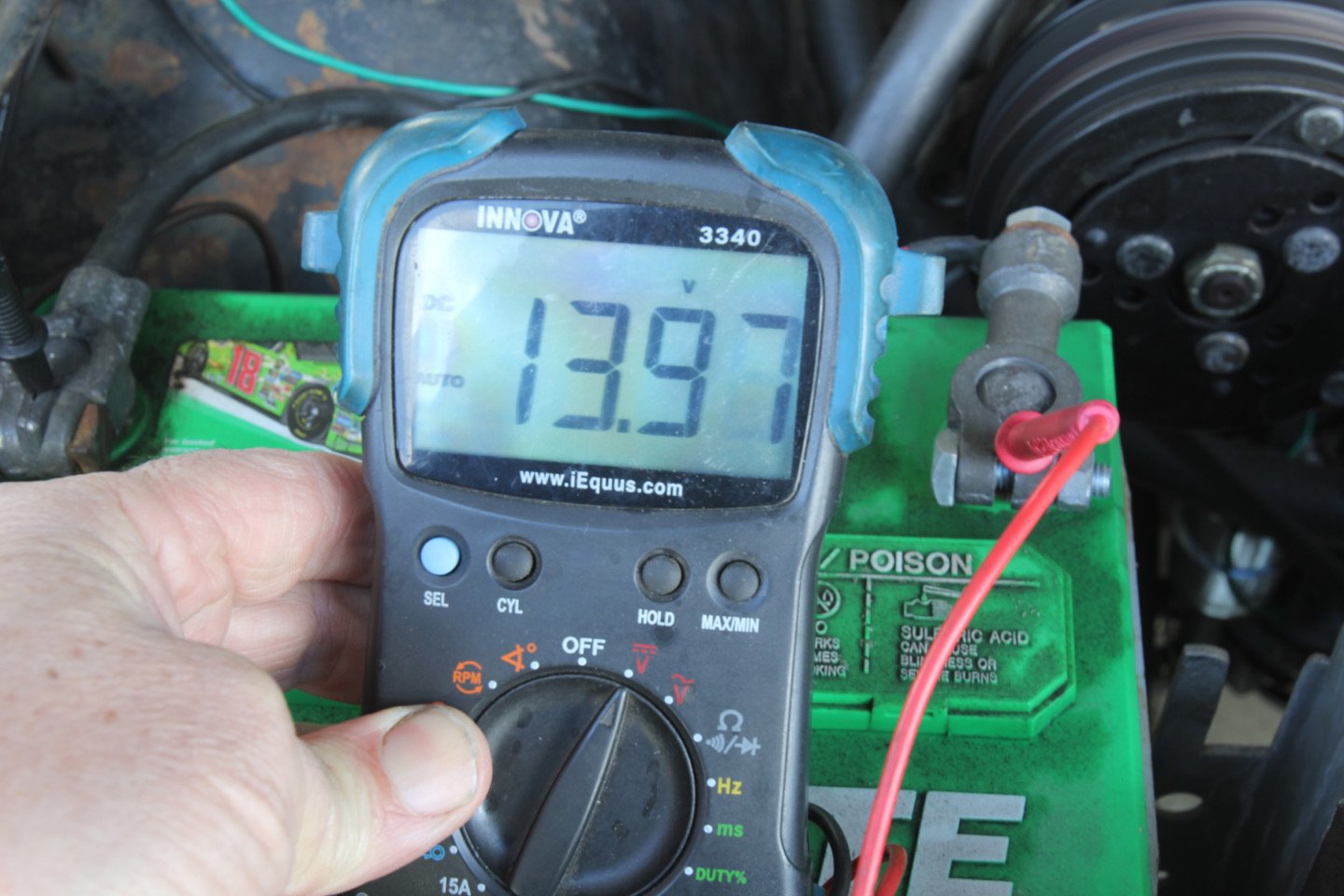
A common charging arrangement issue with older cars is excessive resistance between the alternator and the battery. A quick examination with the engine idling is to turn on several electrical accessories like headlights and the heater fan. Then, test voltage at the rear of the alternator and compare that to the voltage at the battery. If the voltage at the battery is inside 0.5-volt of the alternator voltage, then the charge wire is okay. If it drops more than than 0.06-volt — like here at 13.97 volts — the charge wire is too minor, or there is resistance at the connections.
All tardily-model alternators use an electronic voltage regulator. If your car is like this Chevelle and has a voltmeter or factory ammeter gauge without a charging system warning light, a resistor must be wired into the warning light circuit. Substantially, the resistor takes the place of the load created by the alarm light.
We were curious equally to why this resistor is important, and according to Painless engineer Eric Cowden, "The resistor limits the amperage the exciter wire can supply. In manufactory applications, either a charge-indicator lite or ECM provides this i amp or less, switched 12-volt source. Without this resistance, also much amperage reaches the regulator and causes it to burn up."
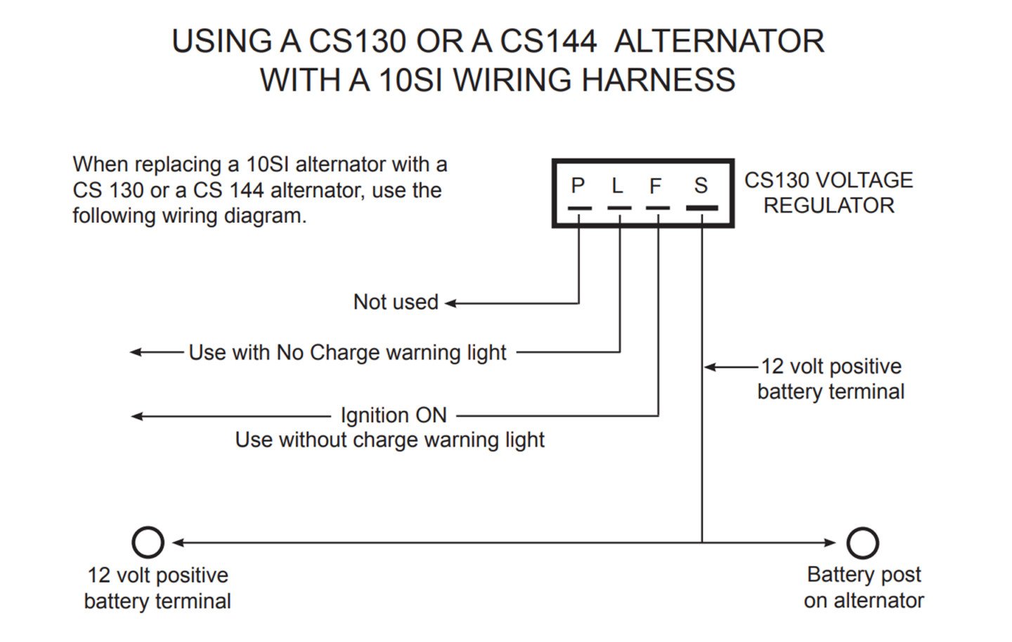
This Painless Performance illustration shows how the CS-130 and CS-144 alternators should be wired. The "Due south" connexion on the alternator (left image) is the larger pin on the far left while the "Fifty" is second from the right. Note the cartoon shows the external shape of the connector as rounded on 1 end while the internal shape is rectangular.
Cowden added this further explanation, "if you take watts divided by volts, you get amps. So, with this resistor, under normal charging circumstances, you are never putting more than than 0.5 amp to the alternator." Hither'southward the math that backs that up:
5 watts / 14 volts = 0.35 amps
Of course, simply wiring the Painless connector to a warning light accomplishes the aforementioned affair as the resistor, so one or the other is all that is needed. This is true for all later model alternators with internal voltage regulators and is why Painless includes the resistor in every pigtail conversion.
We make this bespeak because it is possible to purchase a replacement alternator pigtail from near whatever motorcar parts store. These are oftentimes less expensive, but non packaged with a resistor. If y'all are using a standard pigtail (peradventure pulled from a junkyard vehicle), you need to know which wire is the voltage-sensing wire and which one is the exciter wire that needs either a accuse-indicator light or a resistor.
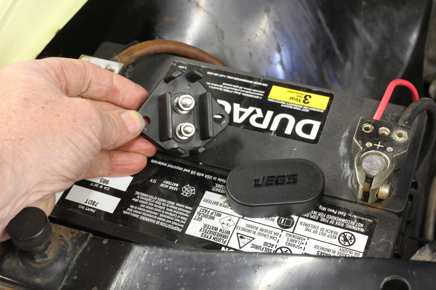
We've used these two-post last blocks, available from Jegs, for mounting both live battery power and switched power. This makes an fantabulous spot for the voltage-sensing wire connection when this concluding cake is mounted near the battery.
To proceed this story brief, nosotros have not taken a deep dive into physically mounting these unlike alternators to various engines, as this can get somewhat complicated. To simplify this as much as possible, the newer CS130 and CS144 alternators are a great selection for Gen I pocket-sized- and big-block Chevys, while the CS-130D is usually used on factory accessory drives for LS engines.
With this review of the wiring harness differences, updating your charging arrangement should not exist very intimidating. It's elementary in one case you understand how the system works.

Source: https://www.chevyhardcore.com/tech-stories/ignition-electronics-efi/alternator-upgrade-wiring-tips-for-popular-gm-charging-systems/
Posted by: irizarryriplat.blogspot.com
0 Response to "How To Repair An Alternator Bearings On Chevy Suburban"
Post a Comment